What is the Otto cycle and the Diesel cycle, and how are they defined?
Inhibition String Theory / / April 02, 2023

Industrial Engineer, MSc in Physics, and EdD
Both constitute the theoretical models that are used to describe the gas thermodynamic cycles that are carried out. carried out in four-stroke internal combustion engines with spark ignition and self-ignition respectively.
The Otto cycle owes its name to the fact that it was the German engineer Nikolaus Otto who in 1876 developed this spark ignition four-stroke engine, based on the model proposed in 1862 by Beau de Rochas. This engine executes four thermodynamic processes in two mechanical cycles. For its part, the Diesel cycle was developed between 1890 and 1897 by Rudolft Diesel in Germany for the transport company MAN, with the intention to manufacture engines with higher performance than steam engines from other fuels that offer higher efficiencies. This creation has been refined ever since, and for example, in 1927 the BOSH company launched a pump injection for Diesel that helped to reduce fuel consumption, which is more economical than the gasoline.
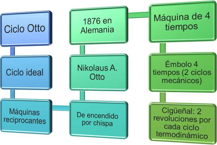
The image shows a scheme with the most representative elements that describe an Otto cycle
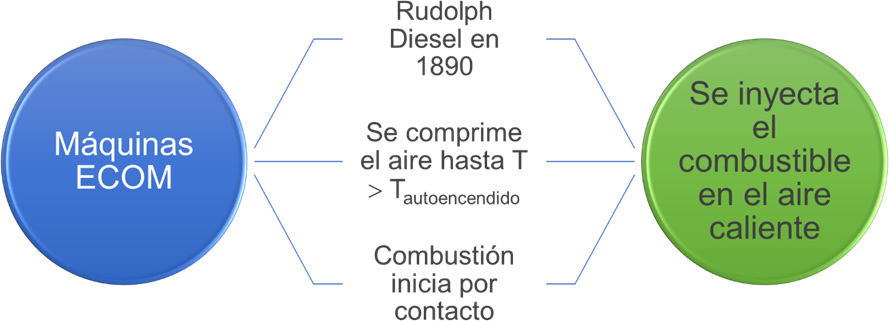
Diesel cycles theoretically describe the operation of ECOM engines (compression ignition engines). The diagram shows some features of this cycle.
Thermodynamic processes of internal combustion engines
The general, four-stroke reciprocating engines in practice, are made up of four processes: intake, compression, expansion, and exhaust.
In both spark ignition engines and Diesel engines, during the intake process, the intake valve opens in the cylinder to allow air to enter (in the case of diesel engines). Diesel engines) and air and fuel (in spark ignition engines), which occurs at atmospheric pressure (for this, a pressure inside the cylinder is required lower). The entry of this volume into the cylinder moves the piston towards the bottom dead center (BDC) until reaching the maximum volume where the intake valve closes.
During the compression process, the intake and exhaust valves remain closed and the piston moves towards the upper dead point (TDC), compressing the contents of the chamber until reaching the volume minimum. Unlike spark ignition engines, where the compression ratio is around than 11, in the cylinders of Diesel engines this ratio is required to be higher, approximately 18. This longer path allows higher temperatures to be reached to guarantee the autoignition of the fuel in the following process, that is, the temperature of the air at the end of the compression process, must be higher than that given in the self-ignition of the fuel so that it can ignite when entering the compression chamber. combustion.
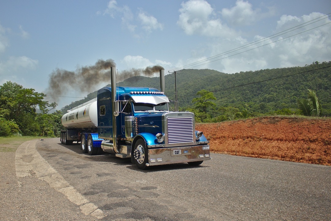
Diesel cycles require larger cylinders than gasoline or gas engines, so both are commonly used in trucks or large means of transport as well as in the agroindustry.
The process that follows is that of expansion or power stroke, and it begins when the piston reaches the top dead center. In spark ignition engines, combustion is practically instantaneous and occurs through the ignition of a spark generated by the spark plug, which causes the combustion of the mixture of air and fuel. In the case of ECOM engines, the process is slightly slower, starting when the piston is at TDC and the injectors spray fuel into the chamber. When diesel or gas oil comes into contact with air at a high temperature, this mixture ignites and drives the piston toward BDC expanding the combustion gases and causing the engine crankshaft to rotate. engine.
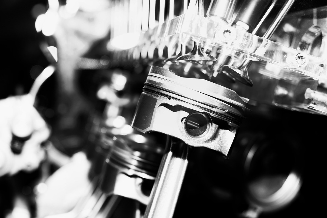
The image shows a cylinder of an internal combustion engine. You can see the valves, and the piston.
Finally, there is the opening of the exhaust valve so that the piston rises and displaces the combustion gases and the cycle begins again.
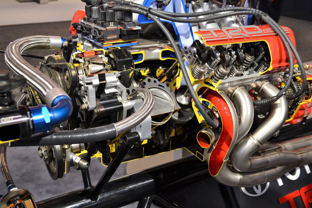
In Diesel engines, spark plugs are not used as in gasoline engines, since the combustion process is produced thanks to the pressure and temperature conditions in the combustion chamber at the moment of injecting the fuel.
In order to simplify the calculations and thermodynamic analysis inside the cylinders of the engines of internal combustion, some assumptions are made, such as standard air considerations and that the processes are reversible. Through these premises, the Otto and Diesel cycles are developed, to form the four processes, as shown in the following image:

The four processes of four-stroke internal combustion engines.
1-2: isentropic compression
2-3: Addition of heat. In Otto cycles, this process is assumed at constant volume (isochore) and in Diesel cycles it approaches one at constant pressure (isobaric).
3-4: isentropic expansion
4-1: Constant Volume Heat Rejection (Isochoral)

The diagram on the left shows the processes that take place in spark ignition engines. In practice, it is an open process that requires an intake of outside air and an expulsion of exhaust gases into the environment. On the right, the simplification of this model is observed as a closed cycle formed by two isentropic processes and two isochores.
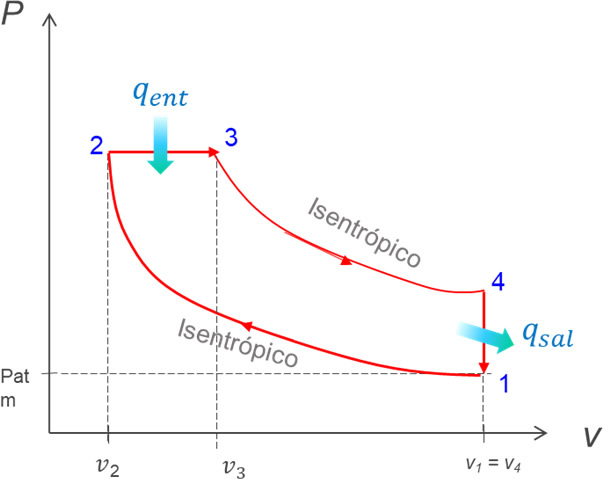
In the Diesel cycle, the intake and exhaust processes are replaced by those of constant pressure heat addition and constant volume heat rejection. Furthermore, the compression and expansion processes are assumed to be isentropic.
Four-stroke internal combustion engines are not only used in the transportation industry. They also have certain applications at a residential and industrial level, for example, to apply cogeneration, and obtain electricity (or mechanical energy), and heat from a single primary source, which would be the fuel used. However, for cogeneration purposes, Otto cycles and gas turbines are more common.
Efficiency of four-stroke internal combustion engines
Like all thermodynamic cycles, gas cycles offer a measure of their performance based on thermal efficiency (ηter), which show the relationship between the net work wneto divided by the heat input qent:
\(_{Ter = }\frac{{{w_{net}}}}{{{q_{ent}}}} = \frac{{{q_{ent}} – {q_{sal}}}}{ {{q_{in}}}} = 1 – \frac{{{q_{salt}}}}{{{q_{in}}}}\)
Where:
whatsalt represents the heat rejected in an isochoric manner.
the qsalt It is determined by the change in internal energy (u) between the states where the heat rejection process occurs, that is, states 4 and 1. These quantities are taken from the steam tables, and in order to locate the values, it is necessary to know two pieces of information about the state, for example, the temperature and the pressure. Additionally, it is required to apply the equation of state (P.v = R.T), and the relation of pressures, volumes, or pressures/relative volumes that occurs between isentropic processes.
In Otto cycles, the heat addition process is carried out at constant volume, therefore the input heat qin is determined by the change in internal energy between states 2 and 3, that is, u3 - or2:
\(_{Ter = } = 1 – \frac{{{u_4} – {u_1}}}{{{u_3} – {u_2}}}\)
In the case of the heat addition process for Diesel cycles, this is assumed to be at constant pressure, and the input heat qin, is calculated from the enthalpy change (h) between the states where this process takes place, that is, between states 3 and 2. With these considerations, the efficiency of a Diesel cycle can be determined using the expression:
\(_{Ter = } = 1 – \frac{{{u_4} – {u_1}}}{{{h_3} – {h_2}}}\)
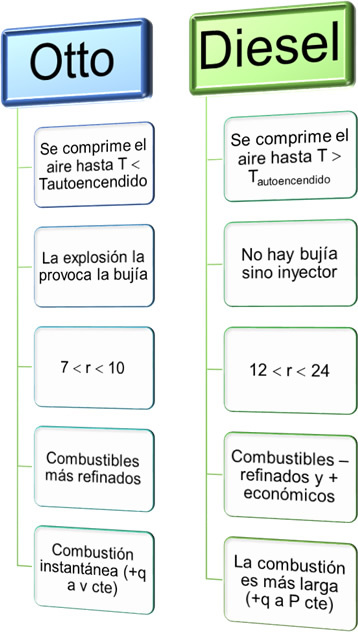
This schematic shows some differences between the Otto cycle and the Diesel cycle. If both engines could operate at the same compression ratio (r), Otto cycles would be more efficient, however in practice, Diesel engines have higher compression ratios.
The compression ratio (r) and intake cutoff (rc)
This dimensionless value is a parameter in gas cycles, and is expressed as the link that occurs over the maximum and minimum volumes of the cylinder:
\(r = \frac{{{V_{max}}}}{{{V_{min}}}}\)
In both the Otto and Diesel cycles, the maximum volume is obtained in states 1 or 4. The minimum volume in the Otto cycle occurs in states 2 and 3, but in Diesel it only occurs in state 2.
The dimensionless constant of specific heats "k" is also defined, and represents the relationship identified with respect to the variables of specific heat at constant pressure (Cp) and specific heat at constant volume (Cv):
\(k = \frac{{{C_p}}}{{{C_v}}}\)
Additionally, in Diesel cycles the cutoff ratio or intake closure is used, which is calculated by dividing the maximum volume by the minimum volume during the heat addition process, that is say:
\({r_c} = {\left( {\frac{{{V_{max}}}}{{{V_{min}}}}} \right) n\;of\;heat} } = \frac{{{V_3}}}{{{V_2}}} = \frac{{{v_3}}}{{{v_2}}}\)
Efficiency of Internal Combustion Engines Using Constant Specific Heat Assumptions
In a gas cycle, it can sometimes be assumed to work under assumptions of specific heats that do not vary with temperature, also called cold air. standard, (however in practice if there is variation), and under this consideration, the thermal efficiency of each cycle is determined with the following expressions:
For the Otto cycle
\(_{Ter = } = 1 – \frac{1}{{{r^{k – 1}}}}\)
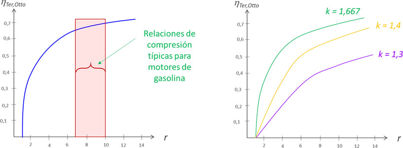
The diagram on the left shows the characteristic range of values for the compression ratio for spark ignition engines. On the right, the variation of the efficiency of an Otto cycle is observed as a function of the compression ratio (r), for different values of k.
For the Diesel cycle
\(_{Ter = } = 1 – \frac{1}{{{r^{k – 1}}}}\left[ {\frac{{{r_c}^k – 1}}{{k\left ( {{r_c} – 1} \right)}}} \right]\)
Wherev is the specific heat of air at constant volume (C.v = 0.718kJ/kg. k), and C.p the specific heat at constant pressure, which for air at ambient conditions is Cp = 1.005kJ/kg. K.
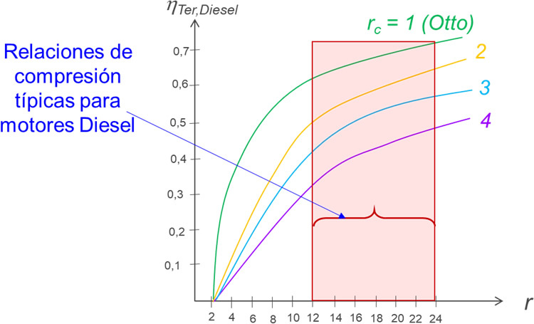
The diagram shows the typical range of compression ratio (r) for Diesel engines, as well as the variation of the thermal efficiency of the cycle for different values of intake cut ratios (rc).


